- 您现在的位置:买卖IC网 > Sheet目录395 > AS3932-BTST (ams)IC RF PROGRAM 16-TSSOP
�� �
�
�AS3932�
�Datasheet� -� D� e� t� a� i� l� e� d� D� e� s� c� r� i� p� t� i� o� n�
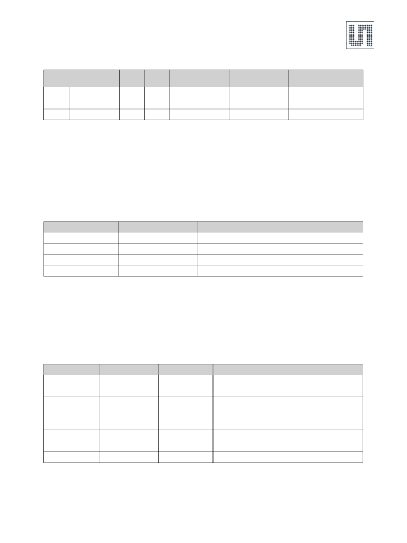
�Table� 19.� Bit� Rate� Setup�
�R7<4>�
�1�
�1�
�1�
�R7<3>�
�1�
�1�
�1�
�R7<2>�
�1�
�1�
�1�
�R7<1>�
�0�
�1�
�1�
�R7<0>�
�1�
�0�
�1�
�Bit� duration� in� RTC�
�clock� periods�
�30�
�31�
�32�
�Bit� rate� (bits/s)�
�1092�
�1056�
�1024�
�Symbol� rate� (Manchester�
�symbols/s)�
�546�
�528�
�512�
�If� the� preamble� is� detected� correctly� the� correlator� keeps� searching� for� a� data� pattern.� The� duration� of� the� preamble� plus� the� pattern� should� not�
�be� longer� than� 40� bits� (see� bit� rate� definition� in� Table� 19� ).� The� data� pattern� can� be� defined� by� the� user� and� consists� of� two� bytes� which� are� stored�
�in� the� registers� R5<7:0>� and� R6<7:0>� .� The� two� bytes� define� the� pattern� consisting� of� 16� half� bit� periods.� This� means� the� pattern� and� the� bit�
�period� can� be� selected� by� the� user.� The� only� limitation� is� that� the� pattern� (in� combination� with� preamble)� must� obey� Manchester� coding� and�
�timing.� It� must� be� noted� that� according� to� Manchester� coding� a� down-to-up� bit� transition� represents� a� symbol� "0",� while� a� transition� up-to-down�
�represents� a� symbol� "1".� If� the� default� code� is� used� (96� [hex])� the� binary� code� is� (10� 01� 01� 10� 01� 10� 10� 01).� MSB� has� to� be� transmitted� first.�
�The� user� can� also� select� (� R1<2>� )� if� single� or� double� data� pattern� is� used� for� wake-up.� In� case� double� pattern� detection� is� set,� the� same� pattern�
�has� to� be� repeated� 2� times.�
�Additionally� it� is� possible� to� set� the� number� of� allowed� missing� zero� bits� (not� symbols)� in� the� received� bitstream� (� R2<6:5>� ),� as� shown� in� the�
�Table� 20� .�
�Table� 20.� Allowed� Pattern� Detection� Errors�
�R2<6>�
�0�
�0�
�1�
�1�
�R2<5>�
�0�
�1�
�0�
�1�
�Maximum� allowed� error� in� the� pattern� detection�
�No� error� allowed�
�1� missed� zero�
�2� missed� zeros�
�3� missed� zeros�
�If� the� pattern� matches� the� wake-up,� interrupt� is� displayed� on� the� WAKE� output.�
�If� the� pattern� detection� fails,� the� internal� wake-up� (on� all� active� channels)� is� terminated� with� no� signal� sent� to� MCU� and� the� false� wake-up� register�
�will� be� incremented� (� R13<7:0>� ).�
�8.6� Wake-up� Protocol� -� Carrier� Frequency� 125� kHz�
�The� wake-up� state� is� terminated� with� the� direct� command� ‘clear_wake’� Table� 12� .� This� command� terminates� the� MCU� activity.� The� termination�
�can� also� be� automatic� in� case� there� is� no� response� from� MCU.� The� time� out� for� automatic� termination� is� set� in� a� register� R7<7:5>� ,� as� shown� in�
�the� Table� 21� .�
�Table� 21.� Timeout� Setup�
�R7<7>�
�0�
�0�
�0�
�0�
�1�
�1�
�1�
�1�
�R7<6>�
�0�
�0�
�1�
�1�
�0�
�0�
�1�
�1�
�R7<5>�
�0�
�1�
�0�
�1�
�0�
�1�
�0�
�1�
�Time� out�
�0� sec�
�50� msec�
�100� msec�
�150� msec�
�200� msec�
�250� msec�
�300� msec�
�350� msec�
�www.ams.com/LF-Receiver/AS3932�
�Revision� 1.7�
�23� -� 34�
�发布紧急采购,3分钟左右您将得到回复。
相关PDF资料
AS500106
TLAPS MAGNET CARRIER
AS5263-HQFT-500
IC ENCODER ROTARY 12BIT 32-QFN
AT 150 B420L
SENSOR CURRENT 150A 30V MOD
AT 150 B5
SENSOR CURRENT 150A MOD
AT 20 B10
SENSOR CURRENT 20A MOD
AT-7666A
SENSOR AMORPHOUS 146X167.5X0.3
AT094
PCB ADAPTER FOR DSA01
AT86RF212-ZUR
TXRX AVR LOW PWR/VOLTAGE 32PQFN
相关代理商/技术参数
AS3932-DB
制造商:ams 功能描述:AS3932 Demo Board Rx & Tx
AS3932-DK
制造商:ams 功能描述:AS3932 Development System
AS3933 DB
制造商:AMS 功能描述:BOARD DEMO FOR AS3933
AS3933 DEV SYSTEM
功能描述:BOARD DEMO FOR AS3933 制造商:ams 系列:- 零件状态:有效 类型:接收器,ASK 频率:125kHz 配套使用产品/相关产品:AS3933 所含物品:2 板,电源,软件 标准包装:1
AS3933BQFT
制造商:ams 功能描述:T&R / QFN 16 (4x4)
AS3933-BQFT
功能描述:射频接收器 RoHS:否 制造商:Skyworks Solutions, Inc. 类型:GPS Receiver 封装 / 箱体:QFN-24 工作频率:4.092 MHz 工作电源电压:3.3 V 封装:Reel
AS3933-BQFT-CUT TAPE
制造商:AMS 功能描述:AS3933 Series 3.6 V 150 KHz 3D Low Frequency Wakeup Receiver - QFN-16
AS3933BTST
制造商:ams 功能描述:T&R / TSSOP 16